Quick links to procedures on this page:
You can fillet, scallop, or chamfer the corners of any curve object, whether it originates from a shape, lines, text, or a bitmap. Filleting produces a rounded corner, scalloping rounds and inverts the corner to create a notch, and chamfering bevels a corner so that it appears flat. CorelDRAW also lets you preview the corners before you apply the changes to them. For information about modifying the corners of squares and rectangles, see Drawing rectangles and squares.
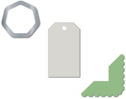
Filleting, chamfering, and scalloping applied to various shapes.
If you modify the corners of a non-curve shape, the shape is automatically converted to curves for you. The changes are applied to all corners unless you select individual nodes. However, you must convert an object to curves manually by using the Convert to curves command before you can select individual nodes. You cannot fillet, scallop, or chamfer a smooth or symmetrical curve; the corner must be created by two straight or curve segments that intersect at an angle of less than 180 degrees.
Setting size values for filleting, scalloping, and chamfering corners
You need to specify the corner radius to determine the size of a filleted or scalloped corner. The radius is measured from the curve’s center to its perimeter. Higher radius values produce more rounded corners or deeper scalloped corners.
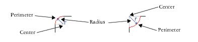
From left to right, you can see the radius of a filleted corner and the radius of a scalloped corner.
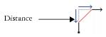
The size value for chamfering a corner represents the distance to set where the chamfer will begin in relation to the original corner. Higher corner size values produce a longer chamfered edge.
The operation is not applied to the corners when the fillet, scallop, or chamfer value is too high. This occurs when the line segments aren’t long enough to apply the radius or chamfer distance. When setting values for these operations, consider that, although the line segments may appear long enough at the beginning of the operation, they shorten as the radius or chamfer values are applied across the object.
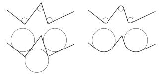
In this example, the circles represent fillet radius settings. The top row shows the proposed fillets on the left and the filleted results on the right. The bottom row shows the proposed fillets on the left, but in the results on the right, not all corners are filleted. After the first fillet is applied, the next corner cannot be filleted because the line segment is not long enough. This corner is skipped, and the final corner is filleted.
| 2 . |
Click Window  Dockers Fillet/Scallop/Chamfer. Dockers Fillet/Scallop/Chamfer. |
| 3 . |
In the Fillet/Scallop/Chamfer docker, choose one of the following options from the Operation list box. |

The Apply button is disabled if no valid objects or nodes are selected.

To select individual nodes using the Shape tool  , you must first convert the object to curves manually by using the Convert to curves command.
| 2 . |
Click Window Dockers Fillet/Scallop/Chamfer. |
| 3 . |
In the Fillet/Scallop/Chamfer docker, choose Chamfer from the Operation list box. |
| 4 . |
Type a value in the Distance box to set where the chamfer will begin in relation to the original corner. |
To select individual nodes using the Shape tool , you must first convert the object to curves manually by using the Convert to curves command.
Copyright 2015 Corel Corporation. All rights reserved.