Sometimes, a drawing plane of a preset drawing profile may need to be customized for the drawing task at hand. You can define the drawing plane interactively by using one of two methods: With 3 axes and From selected parallelogram .
If your drawing contains instances of the Y, Z, and X axes that you need to define the drawing plane, use the With 3 axes method and specify the three axes by dragging in the drawing window. If your drawing doesn’t have all the projected axes you need, you must use a parallelogram that matches the projection of the desired drawing plane.
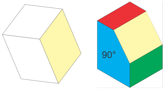
The desired projected plane is shown in yellow. Use the With 3 axes method when your drawing contains references for the three axes (left). Use the From selected parallelogram method when the reference plane (yellow parallelogram) is available.
After you define the drawing plane, you can complete your drawing task. If you need to use the custom drawing plane later, you must save it to a custom drawing profile. You can also customize drawing planes by specifying angle and scale values for the X, Y, and Z axes. For information about specifying angle and scale values for X, Y, and Z axes, see To create or edit a drawing profile.
1 .
Click Window Projected Axes .
2 .
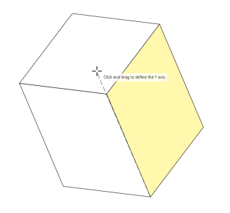
In the Projected Axes docker, enable the With 3 axes option, and click Define .
1 .
Using the Rectangle tool
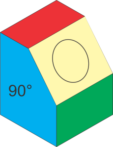
Move, rotate and skew the rectangle to match the desired plane and create the reference parallelogram you need.
2 .
In the Projected Axes docker, enable the From selected parallelogram option.
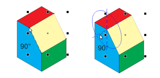
Defining the edge (left) and the adjacent plane (right)
This site works best with JavaScript enabled