You can display dynamic guides to help you move, align, and draw objects in precise relation to other objects. Dynamic guides are temporary guidelines that you can display from the following snap points in objects: center, node, quadrant, and text-baseline end nodes. For more information about snap points and snapping modes, see Using gravity snapping.
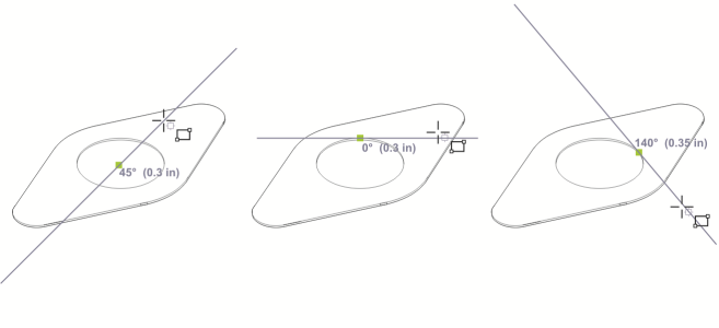
Left to right: The 2-point rectangle tool is used to display dynamic guides from a center snap point, a quadrant snap point, and a tangent snap point.
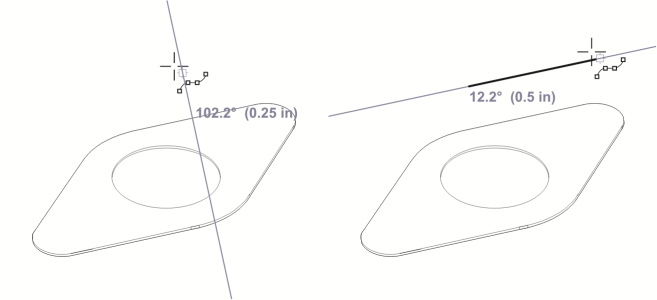
Perpendicular dynamic guide (left) and parallel dynamic guide (right)

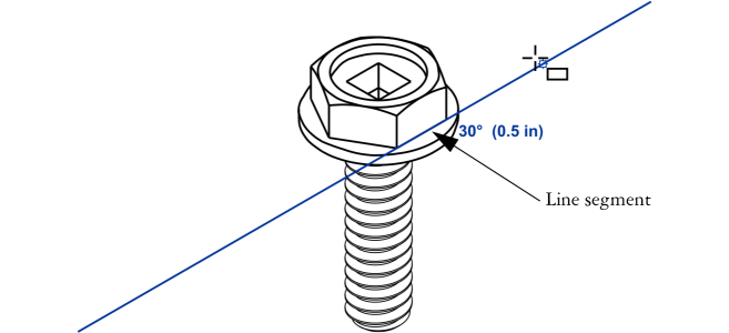
This dynamic guide is an extension of a line segment.
You can turn off dynamic guides at any time.
| To enable or disable dynamic guides |
|
| 1 . | Click Tools |
| 2 . | In the Alignment and dynamic guides docker, enable or disable the check box in upper-right corner of the Dynamic guides section. |
You can toggle dynamic guides on and off by pressing Shift + Alt +D.
| To display dynamic guides |
|
| 1 . | With dynamic guides enabled, click a drawing tool. |
| 2 . | Move the pointer over and then off a node, center, quadrant, or text-baseline snap point of an object. |
| 3 . | Repeat step 2 with other objects to display other dynamic guides. |
| The snap points you point to are registered in a queue and used to create dynamic guides. |
|
Move the pointer over the edge of an object. When an edge snap point becomes highlighted, press H. Then, display the dynamic guide by moving the pointer off the snap point as if to draw a tangent.
|
|
|
Move the pointer over the edge of an object. When a snap point becomes highlighted, press U. Then, display the dynamic guide by moving the pointer off the snap point as if to draw a perpendicular line.
|
|
|
Click Tools
You can use the 2-point line tool
|
|
|
Click Tools
|
The node, center, quadrant, and text-baseline snap points appear only when the corresponding gravity modes are activated. For more information about snap points and gravity modes, see Using gravity snapping.
You can avoid displaying too many dynamic guides by clicking in the drawing window or by pressing Esc. Either of these actions clears the queue of points.
| To position an object in relation to another object |
|
| 1 . | With dynamic guides enabled, select an object. |
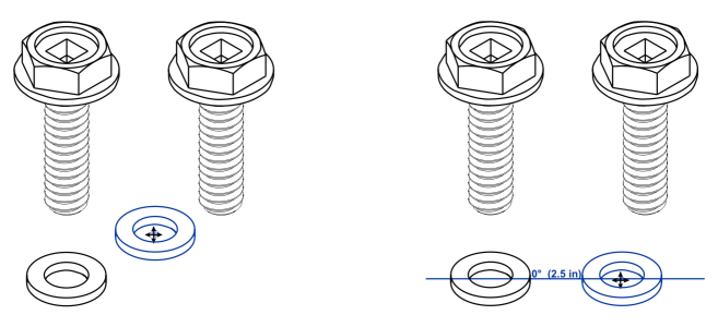
| 2 . | Drag the object to a node, center, quadrant, or text-baseline snap point of the target object. |
| 3 . | When the snap point of the target object becomes highlighted, drag the object along the dynamic guide to position it. |
The node, center, quadrant, and text-baseline snap points are displayed only when the corresponding gravity modes are activated. For more information about snap points and gravity modes, see Using gravity snapping.
| To draw an object in relation to another object |
|
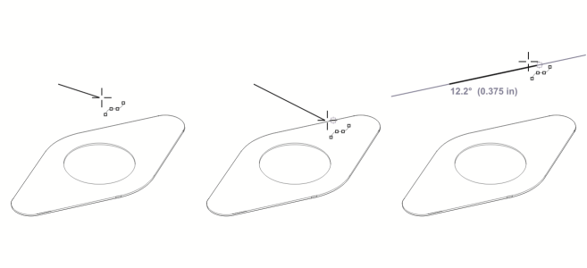
| 1 . | With dynamic guides enabled, click a drawing tool. |
| 2 . | Move the pointer over a node, center, quadrant, or text-baseline end-node snap point of an object. |
| 3 . | When the snap point becomes highlighted, move the pointer to display a dynamic guide. |
| 4 . | Move the pointer along the dynamic guide to the point where you want to draw, and drag to draw an object. |
| To draw parallel lines |
|
| 1 . | Click Tools |
| 2 . | Ensure that the Generate parallel guides button is enabled. |
| 3 . | Draw a straight line or an object that contains straight line segments. |
| 4 . | Using the 2-point line tool |
| 5 . | Move the pointer back to where you want to draw the parallel line. |
| 6 . | When a parallel dynamic guide appears, continue to drag along the guide until the line is the length you want. |
With the help of parallel dynamic guides, you can use the 3-point rectangle tool ![]() to draw rectangles that are parallel to straight line segments.
to draw rectangles that are parallel to straight line segments.
| To position an object at the intersection of dynamic guides |
|
| 1 . | With dynamic guides enabled, select an object. |
| If you want to move the object by a specific snap point, move the pointer over the snap point until the point becomes highlighted. |
| 2 . | Drag the object to an eligible snap point on another object, and continue to drag until a dynamic guide appears. |
| Don’t release the mouse button. |
| 3 . | Drag the object to another eligible snap point, and don’t release the mouse button. |
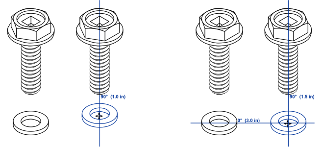
| 4 . | When the snap point becomes highlighted, continue to drag until another dynamic guide appears where the two dynamic guides would intersect. |
| 5 . | When the intersection point appears, release the mouse button. |
| To set options for dynamic guides |
|
| 1 . | Click Tools |
| 2 . | In the Alignment and dynamic guides docker, click the Dynamic guides button |
| 3 . | Perform one or more tasks from the following table. |
|
Open the Line style picker, and choose a line style.
|
|
|
Open the Line color picker, and choose a color.
|
|
|
Click the Display screen tips button
|
|
|
Click the Snap to tick spacing button
|
|
|
When you enable an angle check box, a preview of the dynamic guide appears in the Guides preview window.
|
|
|
Type a value in the Custom angle box, and click the Add custom angle button
|
|
|
Select a dynamic guide in the list, and click the Delete custom angle button
|
|
|
Click the Select all button
|
|
|
Click the Deselect all button
|
Copyright 2018 Corel Corporation. All rights reserved.