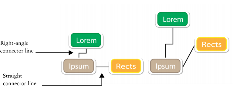
You can draw connector lines between objects. Objects stay connected by these lines even when you move one or both objects. Connector lines, which are also known as "flow lines", are used in technical drawings such as diagrams, flowcharts, and schematics. For information about drawing flowchart shapes, see Drawing predefined shapes.
Using the controls on the property bar, you can modify the width and style of a connector line as well as apply arrowheads. For more information, see Formatting lines and outlines. You can also change the color of connector lines.
When you move objects, their connector lines remain attached.
You can draw callout lines that label and draw attention to objects.
To use connector and callout lines with precision, you need to snap them to specific nodes in objects. For more information about snapping and snapping modes, see Snapping objects.
| To draw a connector line between two or more objects |
|
| 1 . | In the toolbox, click the Straight-line connector tool button, and then click one of the following: |
| • | Straight-line connector tool |
| • | Right-angle connector tool |
| • | Rounded right-angle connector tool |
| 2 . | Drag from a node on one object to a node on another object. |
|
Using the Shape tool
|
|
|
Using the Shape tool
|
|
|
Using the Shape tool
|
|
|
Using the Shape tool
|
| To change the direction of a connection line |
|
| 1 . | In the toolbox, click the Edit anchor tool |
| 2 . | Click the anchor point from which you want to change the connector line direction. |
| 3 . | On the property bar, click the Adjust anchor direction button |
| 4 . | In the Adjust anchor direction box, type one of the following values: |
| • | 0 — directs the connector line to the right |
| • | 90 — directs the connector line straight up |
| • | 180 — directs the connector line to the left |
| • | 270 — directs the connector line straight down |
You can change the direction of only right-angle connector lines.
| To add an anchor point to an object |
|
| 1 . | In the toolbox, click the Edit anchor tool |
| 2 . | Double-click anywhere on an object to add the anchor point. |
By default, anchor points that you add to an object are not available as snap points for a connector line when the object is moved around in the drawing. To make an anchor point available as a snap point, select it with the Edit anchor tool, and click the Auto anchor button ![]() on the property bar.
on the property bar.
By default, the position of the anchor point is calculated relative to its position on the page. You can set the anchor point position relative to the object that it is attached to, which is useful if you want to set anchor points in the same relative position in multiple objects. To set the anchor point position relative to the object, select the anchor point with the Edit anchor tool ![]() . On the property bar, click the Relative to object button
. On the property bar, click the Relative to object button ![]() , and type the coordinates in the Anchor position box.
, and type the coordinates in the Anchor position box.
| To move or delete an anchor point |
|
|
Using the Edit anchor tool
|
|
|
On the property bar, click the Delete anchor button
|
| To set a connector line to flow around objects |
|
| 1 . | Using the Pick tool |
| 2 . | Click Window |
| 3 . | In the Object properties docker, click Summary to display additional options. |
| 4 . | Enable the Wrap connector line check box. |
To flow around an object, a connector line must be attached to the object by at least one end.
| To add a text label to a connector line |
|
| 1 . | In the toolbox, click one of the following tools. |
| • | Straight-line connector tool |
| • | Right-angle connector tool |
| • | Rounded right-angle connector tool |
| 2 . | Double-click the connector line. |
| A text cursor appears. |
| 3 . | Type the text. |
As you move the connector line, the text label remains attached to it.
| To draw a callout |
|
| 1 . | In the toolbox, click the 3-Point callout tool |
| The 3-Point callout tool is located on the Dimension tools flyout. |
| 2 . | Click where you want the first callout segment to start, and drag to where you want the first segment to end. |
| 3 . | Click where you want the second segment to end. |
| A text cursor |
| 4 . | Type the callout text. |
|
Choose a shape from the Callout shape box on the property bar.
|
|
|
Type a value in the Gap box.
|
If you want to edit the callout line and callout text independently of each other, as a line and a text object, you must first separate the callout line from the callout text by clicking Object ![]() Break callout apart.
Break callout apart.
![]()
Not all suite components documented in this Help are available in our Trial, Academic, and OEM versions. Unavailable components may include Corel applications, product features, third-party utilities, and extra content files.
Copyright 2018 Corel Corporation. All rights reserved.