Define a projected drawing plane interactively
Sometimes, a drawing plane of a preset drawing profile may need to be customized for the drawing task at hand. You can define the drawing plane interactively by using one of two methods: With 3 axes and From selected parallelogram.
If your drawing contains instances of the Y, Z, and X axes that you need to define the drawing plane, use the With 3 axes method and specify the three axes by dragging in the drawing window. If your drawing doesn’t have all the projected axes you need, you must use a parallelogram that matches the projection of the desired drawing plane.
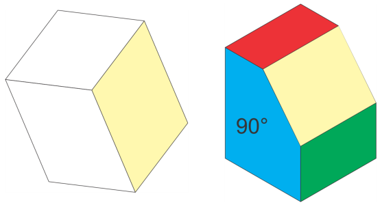
The desired projected plane is shown in yellow. Use the With 3 axes method when your drawing contains references for the three axes (left). Use the From selected parallelogram method when the reference plane (yellow parallelogram) is available.
After you define the drawing plane, you can complete your drawing task. If you need to use the custom drawing plane later, you must save it to a custom drawing profile. You can also customize drawing planes by specifying angle and scale values for the X, Y, and Z axes. For information about specifying angle and scale values for X, Y, and Z axes, see To create or edit a drawing profile.
To define the drawing plane by setting the X, Y, and Z axes interactively

1
Click
Window  Projected Axes
.
2
In the
Projected Axes docker, enable the
With 3 axes option, and click
Define.
3
In the drawing window, click and drag to define the Y axis. You must follow the direction of the Y axis on the interactive cube in the
Projected Axes docker.
4
In the drawing window, click and drag to define the X axis, following the direction of the X axis on the interactive cube.
5
Click and drag to define the Z axis.
6
Use any of the drawing tools to draw on the drawing plane you just defined.
To draw on the defined plane later, you must save the custom drawing profile. Click the
Save button

in the
Projected Axes docker, and specify the location and file name of the custom drawing profile.
To define the drawing plane by using a parallelogram
1
Using the
Rectangle tool

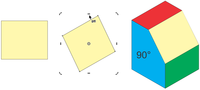
, draw a rectangle. Move, rotate and skew it to match the drawing plane you want to define.
Move, rotate and skew the rectangle to match the desired plane and create the reference parallelogram you need.
2
In the
Projected Axes docker, enable the
From selected parallelogram option, and click
Define.
The
Define button becomes available only if the parallelogram is selected.
3
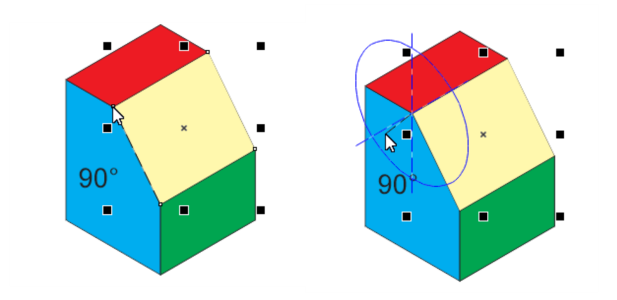
To define the edge that is shared by the desired drawing plane and the adjacent perpendicular projected plane, click to set the first point, and then drag to where you want the second point to be.
An elliptical preview appears in the current projected view.
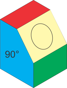
4
Move the preview so that it represents the correct adjacent plane — Top (red), Front (blue), or Right (green), and click. The correct adjacent plane must match the selected projected plane in the
Projected Axes docker. In the example shown in this procedure, it is the Front (blue) plane.
The values for X, Y, and Z axes in the
Projected Axes docker are automatically updated to reflect the plane you defined. The parallelogram can be discarded.
Defining the edge (left) and the adjacent plane (right)
5
Use any of the drawing tools to draw on the active drawing plane you just defined.
To draw on the defined plane later, you must save the custom drawing profile. Click the
Save button
in the
Projected Axes docker, and specify the location and file name of the custom drawing profile.