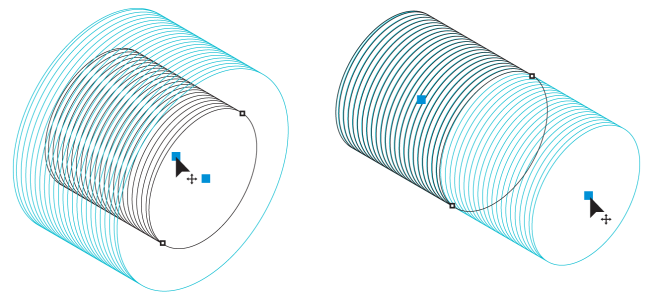
Draw well and thread shapes
You can draw thread and well shapes in projected view. These projected shapes are useful for creating illustrations of bolts, nuts, and threaded holes.
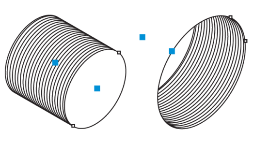
A thread shape and a well shape
You can draw thread and well shapes by starting from the center point of their ellipses or by specifying three points. With the 3-point method, you specify two points for the major axis of the ellipse and one for the length of the shape. The 3-point method is especially useful for adding threads to existing shapes because it uses the edges of the shape to define the thread diameter. For example, you can add threads to bolts, imported from XVL Studio or from CAD drawings, and you can remove the outer lines from the threads to prevent overlapping lines.
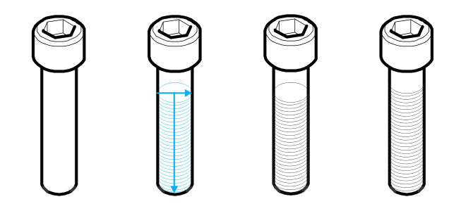
Left to right: An imported bolt; a thread shape is added; the outer lines of the thread shape are removed.
You can adjust the length and radius of the threads and wells by specifying values or by moving their control handles in the drawing window. You can set the distance from the first thread to the start of the object and the distance from the last thread to the end of the object.
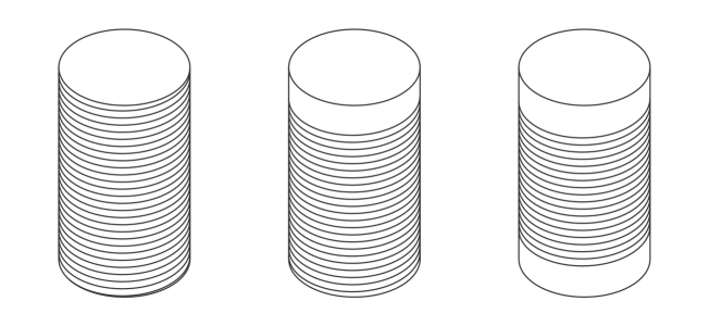
From left to right: Default distance thread values, increased distance to the start of the object, increased distances to both start and end.
You can also adjust the pitch, which is the distance in projected space from one thread to the next. Alternatively, you can adjust the number of threads per inch.
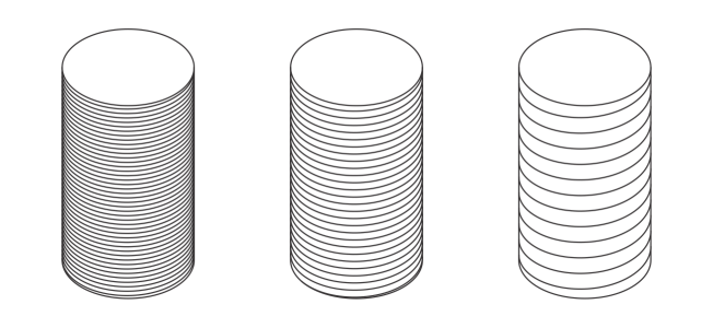
Thread shapes with different pitch values
You can remove the outer lines (border) from thread and well shapes. After removing the outer lines, you can still adjust the properties of thread and well shapes.
To draw a thread shape from the center point of its ellipse

1
Click the
Thread tool

.
2
Click the
Center-Point Thread button

on the property bar.
3
Drag in the drawing window to set the radius of the shape, then move the pointer to set the length, and click.
To add a thread to a shape by specifying three points

1
Click the
Thread tool

in the toolbox.
2
Click the
3-Point Thread button

on the property bar.
3
Snap the pointer to an edge gravity source on the side of the shape where you want the major axis of the ellipse to start.
4
Drag to the opposite side of the shape, and release the mouse button when the perpendicular gravity source is displayed.
5
Drag until the preview reaches the point where you want the thread to end, and click.
6
To remove overlapping lines, click the
Remove Border button

on the property bar.
Adding a thread shape to an imported bolt
To draw a well shape from the center point of its ellipse

1
Click the
Well tool

.
2
Click the
Center-Point Well button

on the property bar.
3
Drag in the drawing window to set the radius of the shape, then move the pointer to set the length, and click.
To draw a well shape by specifying three points

1
Click the
Well tool

.
2
Click the
3-Point Well button

on the property bar.
3
Click in the drawing window where you want the major axis of the ellipse to start, drag to where you want the axis to end and release the mouse button.
4
Move the pointer to set the length of the shape, and click.
If you are adding the well shape to an existing shape, click the
Remove Border button

on the property bar to remove overlapping lines.
To modify a thread or well shape

1
Click one of the following tools:
•
Thread 
•
Well 
2
Click the projected shape, and perform any of the following tasks.
|
|
|
|
|
Type a value in the top portion of the Radius and length box on the property bar. |
|
|
Type a value in the bottom portion of the Radius and length box on the property bar. |
Set the pitch of a thread or well shape |
Click the Pitch button  on the property bar, and type a value in the Pitch box. Pitch values are in millimeters. |
Set the number of threads per inch for a thread or well shape |
Click the Threads per inch button  on the property bar, and type a value in the Threads per inch box. |
Set the distance between the start of a well or thread shape and the first thread |
Type a value in the top portion of the Distance from start or end box. |
Set the distance between the end of a well or thread shape and the last thread |
Type a value in the bottom portion of the Distance from start or end box. |
Hide or show the outer lines of a thread or well shape |
Click the Remove Border button  . |

The radius, length, and distance values are applied in projected space.
To adjust a thread or well shape by using control handles

1
Using a projected shape tool, click the shape to display the control handles.
2
Point to a control handle, and when the cursor changes to an arrow, perform any of the following tasks:
|
|
|
|
|
Drag the radius control handle. |
|
|
Drag the length control handle. |
Using control handles to adjust the radius (left) and length (right) of a thread shape
