To draw a connector line between two or more objects
To change the direction of a connection line
To add an anchor point to an object
To move or delete an anchor point
To set a connector line to flow around objects
To add a text label to a connector line
You can draw connector lines between objects. Objects stay connected by these lines even when you move one or both objects. Connector lines, which are also known as "flow lines", are used in technical drawings such as diagrams, flowcharts, and schematics. For information about drawing flowchart shapes, see Predefined shapes.
Using the controls on the property bar, you can modify the width and style of a connector line as well as apply arrowheads. For more information, see Format lines and outlines. You can also change the color of connector lines.
When you move objects, their connector lines remain attached.
You can draw callout lines that label and draw attention to objects.

To use connector and callout lines with precision, you need to snap them to specific nodes in objects. For more information about snapping and snapping modes, see Snap objects.
| To draw a connector line between two or more objects |
|
| 1 . | In the toolbox, click the Connector tool  button, and then on the property bar click one of the following: button, and then on the property bar click one of the following: |
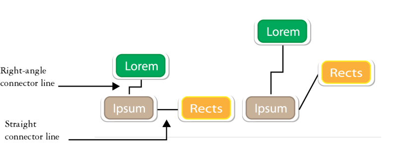
| • | Straight-line connector tool — to create a straight connector line at any angle |
| • | Right-angle connector tool |
| • | Rounded right-angle connector tool |
| 2 . | Drag from a node on one object to a node on another object. |
|
Using the Shape tool
|
|
|
Using the Shape tool
|
|
|
Using the Shape tool
|
|
|
Using the Shape tool
|
| To change the direction of a connection line |
|
| 1 . | In the toolbox, click the Anchor editing tool |
| 2 . | Click the anchor point from which you want to change the connector line direction. |
| 3 . | On the property bar, click the Adjust anchor direction button |
| 4 . | In the Adjust anchor direction box, type one of the following values: |
| • | 0 — directs the connector line to the right |
| • | 90 — directs the connector line straight up |
| • | 180 — directs the connector line to the left |
| • | 270 — directs the connector line straight down |
You can change the direction of only right-angle connector lines.
| To add an anchor point to an object |
|
| 1 . | In the toolbox, click the Anchor editing tool |
| 2 . | Double-click anywhere on an object to add the anchor point. |
By default, anchor points that you add to an object are not available as snap points for a connector line when the object is moved around in the drawing. To make an anchor point available as a snap point, select it with the Anchor editing tool, and click the Auto anchor button ![]() on the property bar.
on the property bar.
By default, the position of the anchor point is calculated relative to its position on the page. You can set the anchor point position relative to the object that it is attached to, which is useful if you want to set anchor points in the same relative position in multiple objects. To set the anchor point position relative to the object, select the anchor point with the Anchor editing tool ![]() . On the property bar, click the Relative to object button
. On the property bar, click the Relative to object button ![]() , and type the coordinates in the Anchor position box.
, and type the coordinates in the Anchor position box.
| To move or delete an anchor point |
|
|
Using the Anchor editing tool
|
|
|
On the property bar, click the Delete anchor button
|
| To set a connector line to flow around objects |
|
| 1 . | Using the Pick tool |
| 2 . | Click Window |
| 3 . | In the Properties docker, click Summary to display additional options. |
| 4 . | Enable the Wrap connector line check box. |
To flow around an object, a connector line must be attached to the object by at least one end.
| To add a text label to a connector line |
|
| 1 . | In the toolbox, click the Connector tool |
| • | Straight-line connector tool |
| • | Right-angle connector tool |
| • | Rounded right-angle connector tool |
| 2 . | Double-click the connector line. |
| A text cursor appears. |
| 3 . | Type the text. |
As you move the connector line, the text label remains attached to it.
| To choose default settings for connector lines |
|
| 1 . | Click Tools |
| 2 . | In the left pane of the dialog box that appears, click Connector. |
| 3 . | To limit snapping and attaching connector lines to only anchor points in objects, disable the Use geometric anchor points as snapping points check box. When this check box is enabled, you can snap and attach connector lines to edge nodes, center nodes and other geometric points in an object. |
| 4 . | To increase or decrease the distance between connector lines and objects, type a higher or lower value in the Route distance from object box. This setting doesn’t apply to straight connector lines. |
| To draw a callout |
|
| 1 . | In the toolbox, click the 3-Point callout tool |
| The 3-Point callout tool is located on the Dimension tools flyout. |
| 2 . | Click where you want the first callout segment to start, and drag to where you want the first segment to end. |
| 3 . | Click where you want the second segment to end. |
| A text cursor |
| 4 . | Type the callout text. |
|
Choose a shape from the Callout shape box on the property bar.
|
|
|
Type a value in the Gap box.
|
If you want to edit the callout line and callout text independently of each other, as a line and a text object, you must first separate the callout line from the callout text by clicking Object ![]() Break callout apart.
Break callout apart.
![]()
The features documented in the Help are available in the full version of CorelDRAW Graphics Suite 2019. Some features may not be available in this version of the product.