Quick links to procedures on this page:
• |
• |
• |
• |
• |
• |
• |
• |
You can draw connector lines, also known as “flow lines,” in flowcharts and wiring diagrams to link shapes and demonstrate how different elements in the drawing are connected. After you attach a connector line to an object, it remains attached to the object even when you move it. You can also leave an end of a connector line unattached to any object, and you can add arrowheads to connector lines to demonstrate the flow direction. For information about drawing flowchart shapes, see Drawing predefined shapes.
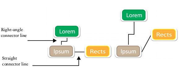
There are several types of connector lines that you can draw. In addition to drawing straight lines, you can draw right-angle connector lines and automatically create right angles as you draw. You can choose between the Right-angle connector tool, which draws a right angle with a sharp corner, and the Right-angle round connector tool, which draws a rounded corner. You can also draw curved connector lines by using either the B-spline connector tool or the Bézier curve connector tool.
Examples of connector lines
Connector lines are attached to objects by anchor points. By default, each object has four anchor points, located on the top, bottom, left, and right sides of the object. Each anchor point appears as a small red diamond on the object. You can move an anchor point along the edge of an object, or you can move an anchor point to any area inside or outside the object. You can also add an anchor point to an object.
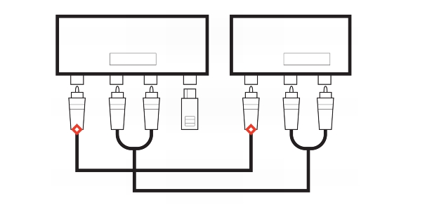
Anchor points appear as small red diamonds.
When you move an object in a drawing, the connector line will snap to the nearest available anchor point. When you add an anchor point to an object, it is not available as a snapping point for connector lines. However, you can set a property on the anchor point to make it available as a snapping point.
You can set an object to repel right-angle, round right-angle, and B-spline connector lines. If the object is in a connector line route, the connector line flows around it. If there is no route for the connector line to follow without intersecting the object, it flows through the object. Straight-line and Bézier-curve connector lines cannot flow around objects.
You can add halos to connector lines. A halo is a mask behind the connector line that makes the line easier to see when it is on top of another object. Usually, the halo is the same color as the page, although you can choose any color you like. Halos also let you modify a connector line without requiring extra node editing.
You can also convert connector lines to curves. When you convert a connector line to a curve, any attached text label changes to an artistic text object.
| To draw a straight connector line |
1. |
Click the Connector tools button, and click the Straight-line connector tool
|
2. |
Click where you want to start the line and drag to where you want to end the line.
|
After you snap a connector line to an anchor point on an object, the connector
line always snaps to that anchor point, even if you move the object around in
the drawing. To ensure that the line connects to the closest available anchor
point when you move the object, release the mouse button to end the connector
line inside the object when drawing the line.
|
| To change the direction of a connector line |
1. |
Click the Connector tools button, and click the Edit anchor tool
|
2. |
Click the anchor point from which you want to change the connector line direction.
|
3. |
On the property bar, click the Adjust anchor direction button
|
4. |
In the Anchor direction box, type one of the following values:
|
• |
0 — directs the connector line to the right
|
• |
90 — directs the connector line straight up
|
• |
180 — directs the connector line to the left
|
• |
270 — directs the connector line straight down
|
You can change the direction only of right-angle and Bézier-curve connector
lines.
|
| To add an anchor point to an object |
1. |
Click the Connector tools button, and click the Edit anchor tool
|
2. |
Double-click anywhere on the object to add an anchor point.
|
By default, anchor points that you add to an object are not available as snap
points for a connector line when the object is moved around in the drawing. To
make an anchor point available as a snap point, select it with the Edit anchor
tool, and click the Auto anchor button
|
By default, the position of the anchor point is calculated relative to the page.
You can set the anchor point position relative to the object that it is attached
to, which is useful if you want to set anchor points in the same relative position
in multiple objects. To set the anchor point position relative to the object,
select the anchor point with the Edit anchor tool
|
| To move or delete an anchor point |
| To set a connector line to flow around objects |
1. |
Using the Pick tool
|
2. |
Click Window |
3. |
In the Property manager docker, click the Summary tab.
|
4. |
Enable the Wrap connector line check box.
|
| To convert a connector line to a curve |
1. |
Select the connector line and the objects it is attached to.
|
2. |
Right-click, and click Convert to curves.
|
You can also convert a curve or a shape, such as a rectangle or an ellipse, to a
connector line by clicking Arrange |
| To add a text label to a connector line |
1. |
Click the Connector tools button, and click a connector tool.
|
2. |
Double-click the connector line.
|
A text cursor appears. |
3. |
Type the text.
|
As you move the connector line, the text label remains attached to it.
|
| To add a halo to a connector line |
1. |
Using the Pick tool
|
2. |
On the property bar, click the Halo properties button
|
3. |
Enable the Halo options check box.
|
4. |
Adjust any of the following settings:
|
• |
Width — lets you specify the width of the halo on each side of the line
|
• |
Color — lets you access a color palette to change the color of the halo, or use the
color of the page
|
• |
Opacity — lets you control the transparency of the halo and the visibility of
objects underneath the halo by specifying a percentage value (with values less
than 100 allowing visibility)
|
To remove a halo from a line, select the line, click the Halo properties button
|
|
|
Copyright 2013 Corel Corporation. All rights reserved.