Dimension lines
You can draw dimension lines to indicate the measurements of objects in a drawing, such as length, width, height, depth, and distance.
Dimension lines indicate the measurements of objects in a drawing.
Types of dimension lines
You can add several types of dimension lines:
•
Vertical or horizontal dimension lines — measure the vertical (y-axis) or horizontal (x-axis) distance between any two
nodes.•
Parallel dimension lines — measure the actual distance between two nodes.
•
Angular dimension lines — measure angles.
•
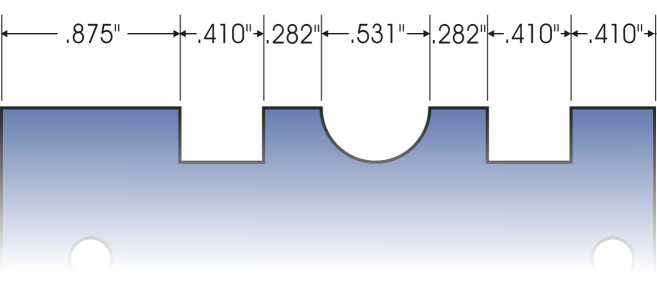
Segment dimension lines — measure the linear distance between the end nodes of a segment, or the linear distance between the two most distant nodes in multiple segments. Segment dimension lines can also measure selected successive segments.
•
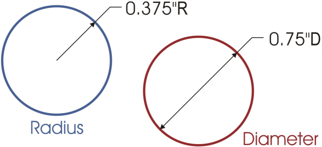
Radial or diametric dimension lines — measure the radius or diameter of a circle or a partial circle.
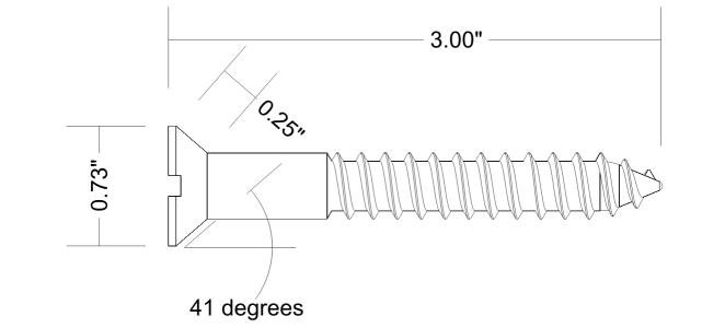
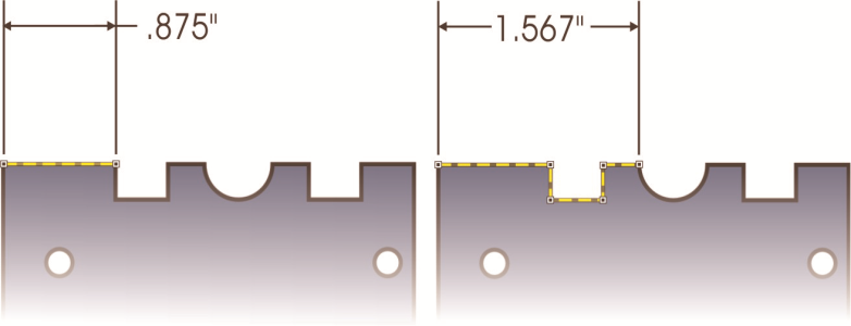
You can measure the distance between the end nodes of a segment (left) or between the two most distant nodes in multiple segments (right).
Dimension lines cannot be used for measuring the length of curved lines, but you can easily view the length of a curve in the Properties docker. For more information, see To view curve properties.
Editing dimension lines
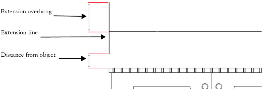
If you are not satisfied with the look and position of the dimension lines you added, you can edit them. You can set how dimension text and lines are displayed. For example, you can choose the unit of measurement, specify the position and font of the dimension units, and add a prefix or suffix to dimension text. You can also customize the extension lines on which dimension lines rest. You can specify the distance between the extension lines and the object that is measured, and the length of the extension overhang. Extension overhang is the portion of the extension line that falls beyond the dimension arrows.
By default, dimension text is dynamic. If you resize the object to which a dimension line is attached, the dimension text is updated automatically to display the new size. However, you can make the dimension text static, if necessary.
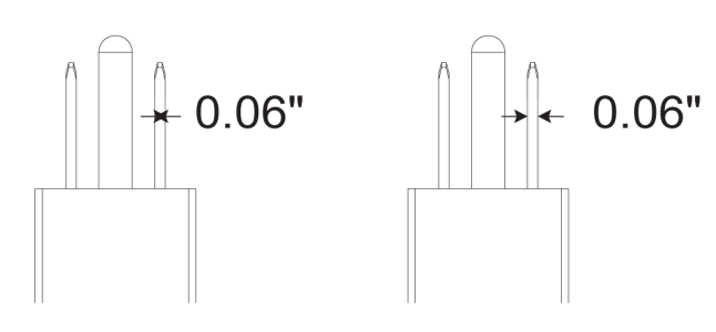
When a dimension line is so small that its arrowheads overlap, the application automatically places them outside the leader lines.
Arrowheads are reversed when a dimension line is too small.
You can break the link between a dimension line and the object it is attached to. This feature can be useful if you want to manipulate the dimension line independently of the object.

Dimension lines cannot be brought into Focus mode, but you can bring dimension text into focus. For more information about Focus mode, see Edit objects in Focus mode.
To draw a vertical, horizontal, or parallel dimension line

1
Click the
Horizontal or vertical dimension tool

or the
Parallel dimension tool

.
2
Click to place the starting point, and drag to where you want to place the endpoint of the
dimension line.
3
Move the pointer to position the dimension line, and click to place the dimension text.
By default, the dimension text is centered on the dimension line.
To draw an angular dimension line
1
Click the
Angular dimension tool

.
2
Click where you want the two lines that measure the angle to intersect, and drag to where you want the first line to end.
3
Click where you want the second line to end.
4
Click where you want the angle label to appear.
To draw a segment dimension line
1
Click the
Segment dimension tool

.
2
Click the segment that you want to measure.
3
Move the pointer to where you want to position the
dimension line, and click where you want to place the dimension text.
|
|
|
Measure the distance between the two most distant nodes in multiple segments |
Using the Segment dimension tool , marquee select the segments, move the pointer to position the dimension line, and click where you want to place the dimension text. |
Measure successive segments automatically |
Click the Automatic successive dimensioning button  on the property bar, and marquee select the segments that you want to measure. Move the pointer to position the dimension line, and click where you want to place the dimension text. |
Segment dimension lines can be applied automatically to selected successive segments.
To draw a radial or diametric dimension line
1
Click the
Radial dimension 
or
Diametric dimension 
tool.
2
Click a circle or an arc, and drag to where you want the line to change direction.
You can hold down the constrain key while dragging to constrain the leader line to the current constrain angle.
3
Move the pointer, and then click to place the dimension text.
If you want to add a symbol to the dimension text, choose a symbol from the
Dimension symbol list box on the property bar.
If you transform a circle to an ellipse after applying a radial or diametric dimension line, the dimension measurement does not appear. When you transform the ellipse back to a circle, the correct measurement is displayed.
Examples of radial and diametric dimension lines
To edit a dimension line
2
Click a topic from the following table for help with accomplishing your task.
|
|
|
Change how dimension units are displayed |
|
Change the distance of the extension lines from the object or the length of the extension overhang |
|
Change the color of dimension lines and other line settings |
|
To set the display of dimension units
2
On the property bar, choose options from the following list boxes:
•
Dimension style — lets you choose fractional, decimal, or standard dimension units
•
Dimension precision — lets you choose a level of precision for the measurements
•
Dimension units — lets you choose the unit of measurement
|
|
|
|
|
Click the Display units button  . |
Specify the position of dimension units |
Click the Text position button  on the property bar, and choose a text position. |
Change the point size and font of dimension units |
Select the dimension text using the Pick tool  . On the property bar, choose a font style from the Font list box, and type a value in the Font size box. |
Specify a prefix or suffix for dimension text |
Type a prefix or suffix in the Prefix or Suffix box on the property bar. |
Hide or show a leading zero with a dimension value |
Click the Show leading zero button  on the property bar. The leading zero appears in dimension lines by default. |
Make dimension text static |
Click the Dynamic dimensioning button  on the property bar. Most dimension line controls on the property bar become unavailable. If you change the size of the object to which the line is attached, the dimension line text is not updated. |
To customize extension lines
2
On the property bar, click the
Extension line options button

.
3
To specify the distance between the extension lines and the object, enable the
Distance from object check box, and type a value in the
Distance box.
4
To specify the length of the extension overhang, enable the
Extension overhang check box, and type a value in the
Distance box.
To break the link between an object and a dimension line
2
Click
Object  Break dimension apart
.
After you break the link between the object and the dimension line, the dimension text is no longer updated automatically when you resize the object.