Quick links to procedures on this page:
• |
• |
• |
• |
• |
• |
You can draw dimension lines to indicate the distance between two points in a drawing or the size of objects. You can add several types of dimension lines:
• |
Parallel dimension lines measure the actual distance between two nodes.
|
• |
Vertical or horizontal dimension lines measure the vertical (y-axis) or horizontal (x-axis)
distance between any two nodes.
|
• |
Angular dimension lines measure angles.
|
• |
Segment dimension lines measure the linear distance between the end nodes of a
segment, or the linear distance between the two most distant nodes in multiple
segments. Segment dimension lines can also measure selected successive segments.
|
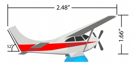
Dimension lines from left to right: Angular, Horizontal, and Vertical
You can set how dimension text and lines are displayed. For example, you can choose the unit of measurement, specify the position and font of the dimension units, and add a prefix or suffix to dimension text. You can also set default values for all new dimension lines that you create.
You can customize the extension lines on which dimension lines rest. You can specify the distance between the extension lines and the object that is measured, and the length of the extension overhang. Extension overhang is the portion of the extension line that falls beyond the dimension arrows.
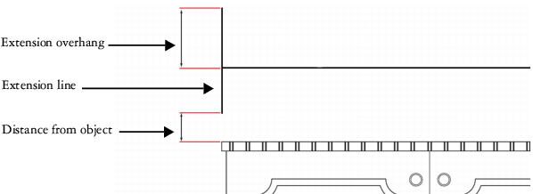
You can customize dimension lines by specifying values for the extension overhang, extension line, and distance from object.
By default, dimension text is dynamic. If you resize the object to which a dimension line is attached, the dimension text is updated automatically to display the new size. You can make the dimension text static, however, if necessary.
To be able to use dimension lines with precision, you need to snap them to specific nodes in objects. For more information about snapping and snapping modes, see Snapping objects.
| To draw a vertical, horizontal, or parallel dimension line |
1. |
Do one of the following:
|
• |
To draw a parallel dimension line, click the Parallel dimension tool
|
• |
To draw a vertical or horizontal dimension line, click the Horizontal or vertical
dimension tool
|
2. |
Click to place the starting point, and drag to where you want to place the endpoint
of the dimension line.
|
3. |
Move the pointer to position the dimension line, and click to place the dimension
text.
|
By default, dimension text is centered on the dimension line. |
| To draw an angular dimension line |
1. |
In the toolbox, click the arrow in the bottom-right corner of the Parallel
dimension tool
|
2. |
Click where you want the two lines that measure the angle to intersect, and drag to
where you want the first line to end.
|
3. |
Click where you want the second line to end.
|
4. |
Click where you want the angle label to appear.
|
| To draw a segment dimension line |
1. |
In the toolbox, click the arrow in the bottom-right corner of the Parallel
dimension tool
|
2. |
Click the segment that you want to measure.
|
3. |
Move the pointer to where you want to position the dimension line, and click
where you want to place the dimension text.
|
Segment dimension lines can be applied automatically to selected successive segments.
| To set the display of dimension units |
1. |
Select a dimension line.
|
2. |
On the property bar, choose options from the following list boxes:
|
• |
Dimension style — lets you choose fractional, decimal or standard dimension
units
|
• |
Dimension precision — lets you choose a level of precision for the
measurements
|
• |
Dimension units — lets you choose the unit of measurement
|
| To set default properties for new dimension lines |
1. |
From the toolbox, double-click the Parallel dimension tool
|
The Dimension tool page of the Options dialog box appears. |
2. |
Specify the dimension style, precision, and units, prefix, and suffix.
|
| To customize extension lines |
1. |
Select a dimension line.
|
2. |
On the property bar, click the Extension lines options button
|
3. |
To specify the distance between the extension lines and the object, enable the
Distance from object check box, and type a value in the Distance box.
|
4. |
To specify the length of the extension overhang, enable the Extension overhang
check box, and type a value in the Distance box.
|
|
|
Copyright 2012 Corel Corporation. All rights reserved.