Quick links to procedures on this page:
• |
• |
• |
Lines are treated the same way as outlines of closed shapes, such as ellipses and polygons. In some programs, outlines are known as strokes or thick lines.
You can change the appearance of both lines and outlines by using the controls in the the Outline section of the Object properties docker, the Outline pen dialog box, and the property bar. For example, you can specify the color, width, and style of lines and outlines.
You can choose a corner style to control the corner shape in lines and choose a line cap style to change the appearance of a line’s endpoints. By default, an outline is applied on top of an object’s fill, but you can apply it behind the fill, with the fill overlapping the outline. You can also link the outline thickness to an object’s size so that the outline increases when you increase the object’s size and decreases when you decrease the object’s size. In addition, you can set the outline to print on top of underlying colors, without removing them during printing.
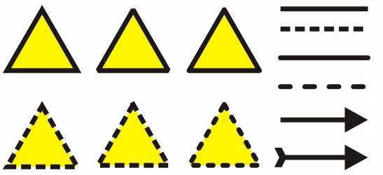
Different corner styles were applied to the upper and lower row of triangles. Different line caps were applied to the lines in the upper-right corner. Arrowheads were applied to the lines in the lower-right corner.
You can set the miter limit to determine the corner shape in objects containing lines that meet at sharp angles. Corners with angles above the miter limit are pointed (mitered); corners with angles below the miter limit are beveled (squared off).
The default line and outline properties for each new object that you draw are as follows:
• |
hairline width
|
• |
black color
|
• |
solid line
|
• |
square corner and line cap styles
|
• |
no arrowheads applied
|
• |
outline applied on top of an object’s fill
|
• |
outline not linked to an object’s size.
|
However, you can change any of these default line and outline properties at any time.
You can create calligraphic outlines. A calligraphic outline varies in thickness, creating the effect of a hand-made drawing.
To create a cuttable outline for devices such as plotters, vinyl cutters and Print-Cut devices, you need to assign the appropriate predefined color (usually CutContour) that is specified by the device manufacturer.
Note that cuttable outlines do not print when identified by the RIP or Print-Cut device. If you want to make the outlines printable, you can use the Arrange ![]() Shaping
Shaping ![]() Boundary command. For more information, see To create a boundary around selected objects.
Boundary command. For more information, see To create a boundary around selected objects.
| To specify line and outline settings |
1. |
Select an object.
|
2. |
Click Window |
3. |
In the Outline section, type a value in the Width box.
|
If the Outline section is not displayed, click Outline. |
4. |
Open the color picker, and click a color.
|
5. |
Choose a line style from the Style box.
|
You can also specify line and outline settings in the Outline pen dialog box.
To access the Outline pen dialog box, click the Outline tool
|
You can also change the outline width of a selected object by typing a value in
the Outline width box on the property bar.
|
| To create a calligraphic outline |
1. |
Select an object.
|
2. |
Click Window |
3. |
In the Outline section, click one of the following buttons to set the shape of
corners:
|
• |
Mitered corners
|
• |
Round corners
|
• |
Beveled corners
|
If the Outline section is not displayed, click Outline. |
4. |
Type a value in the Stretch box to change the width of the pen’s nib.
|
If the Stretch box is not displayed, click the arrow button at the bottom of the Outline section. |
The value range is from 1 to 100, with 100 as the default setting. Reducing the value makes square nibs rectangular and round nibs oval, creating a more pronounced calligraphic effect. |
5. |
Type a value in the Tilt nib box to change the orientation of the pen in relation to
the drawing surface.
|
To reset the Stretch and Tilt nib values to their original values, click the Default button. |
You can also create a calligraphic outline in the Outline pen dialog box. To
access the Outline pen dialog box, click the Outline tool
|
You can also adjust the Stretch and Angle values by dragging in the Nib
shape preview box.
|
| To set the line and outline properties for new objects |
1. |
Using the Pick tool, click on an empty space in the drawing window to deselect all
objects.
|
2. |
In the toolbox, click the Outline tool
|
3. |
In the Change document defaults dialog box, enable the check boxes for the
objects and text whose default settings you want to change, and click OK.
|
4. |
Specify the settings you want in the Outline pen dialog box.
|
|
|
Copyright 2012 Corel Corporation. All rights reserved.