Quick links to procedures on this page:
• |
• |
• |
• |
• |
• |
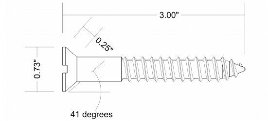
You can draw dimension lines to indicate the measurements of objects in a drawing, such as length, width, height, depth, and distance.
Dimension lines indicate the measurements of objects in a drawing.
You can add several types of dimension lines:
• |
Vertical or horizontal dimension lines — measure the vertical (y-axis) or horizontal
(x-axis) distance between any two nodes.
|
• |
Parallel dimension lines — measure the actual distance between two nodes.
|
• |
Angular dimension lines — measure angles.
|
• |
Segment dimension lines — measure the linear distance between the end nodes of a
segment, or the linear distance between the two most distant nodes in multiple
segments. Segment dimension lines can also measure selected successive segments.
|
• |
Radial or diametric dimension lines — measure the radius or diameter of a circle or
a partial circle.
|
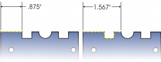
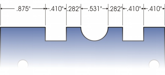
You can measure the distance between the end nodes of a segment (left) or between the two most distant nodes in multiple segments (right).
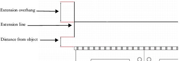
You can set how dimension text and lines are displayed. For example, you can choose the unit of measurement, specify the position and font of the dimension units, and add a prefix or suffix to dimension text. You can also customize the extension lines on which dimension lines rest. You can specify the distance between the extension lines and the object that is measured, and the length of the extension overhang. Extension overhang is the portion of the extension line that falls beyond the dimension arrows.
By default, dimension text is dynamic. If you resize the object to which a dimension line is attached, the dimension text is updated automatically to display the new size. However, you can make the dimension text static, if necessary.
When a dimension line is so small that its arrowheads overlap, the application automatically places them outside the leader lines.
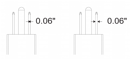
Arrowheads are reversed when a dimension line is too small.
For more information about formatting lines, see Formatting lines and outlines.
| To draw a vertical, horizontal, or parallel dimension line |
1. |
Click the Dimension tools button, and click the Horizontal or vertical
dimension tool
|
2. |
Click to place the starting point, and drag to where you want to place the endpoint
of the dimension line.
|
3. |
Move the pointer to position the dimension line, and click to place the dimension
text.
|
By default, the dimension text is centered on the dimension line. |
| To draw an angular dimension line |
1. |
Click the Dimension tools button, and click the Angular dimension tool
|
2. |
Click where you want the two lines that measure the angle to intersect, and drag to
where you want the first line to end.
|
3. |
Click where you want the second line to end.
|
4. |
Click where you want the angle label to appear.
|
| To draw a segment dimension line |
1. |
Click the Dimension tools button, and click the Segment dimension tool
|
2. |
Click the segment that you want to measure.
|
3. |
Move the pointer to where you want to position the dimension line, and click
where you want to place the dimension text.
|
Segment dimension lines can be applied automatically to selected successive segments.
| To draw a radial or diametric dimension line |
1. |
Click the Dimension tools button, and click the Radial dimension
|
2. |
Click a circle or an arc, and drag to where you want the line to change direction.
|
You can hold down the constrain key while dragging to constrain the leader line to the current constrain angle. |
3. |
Move the pointer, and then click to place the dimension text.
|
If you want to add a symbol to the dimension text, choose a symbol from the Dimension symbol list box on the property bar. |
If you transform a circle to an ellipse after applying a radial or diametric
dimension line, the dimension measurement does not appear. When you
transform the ellipse back to a circle, the correct measurement is displayed.
|
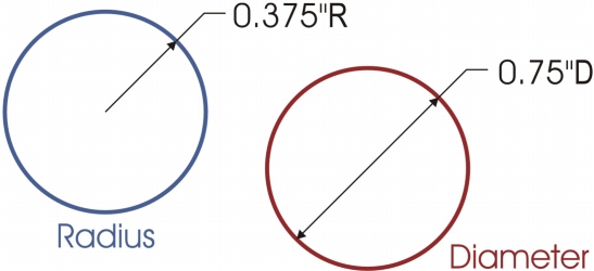
Examples of radial and diametric dimension lines
| To set the display of dimension units |
1. |
Select a dimension line.
|
2. |
On the property bar, choose options from the following list boxes:
|
• |
Dimension style — lets you choose fractional, decimal, or standard dimension
units
|
• |
Dimension precision — lets you choose a level of precision for the
measurements
|
• |
Dimension units — lets you choose the unit of measurement
|
| To customize extension lines |
1. |
Select a dimension line.
|
2. |
On the property bar, click the Extension line options button
|
3. |
To specify the distance between the extension lines and the object, enable the
Distance from object check box, and type a value in the Distance box.
|
4. |
To specify the length of the extension overhang, enable the Extension overhang
check box, and type a value in the Distance box.
|
|
|
Copyright 2013 Corel Corporation. All rights reserved.