
Quick links to procedures on this page:
• |
• |
• |
• |
• |
• |
• |
You can display dynamic guides to help you move, align, and draw objects in precise relation to other objects. Dynamic guides are temporary guidelines that you can display from the following snap points in objects: center, node, quadrant, and text-baseline end nodes. For more information about snap points and snapping modes, see Using gravity snapping.
You can also display dynamic guides that are tangent, perpendicular, or parallel to objects, as well as dynamic guides that are extensions of line segments.
Left to right: The 2-point rectangle tool is used to display dynamic guides from a center snap point, a quadrant snap point, and a tangent snap point.
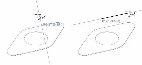
Perpendicular dynamic guide (left) and parallel dynamic guide (right)
As you drag an object along a dynamic guide, you can view the distance between the object and the snap point that was used to create the dynamic guide. You can then position the object precisely. Dynamic guides can also help you draw parallel lines and draw objects in relation to other objects. In addition, you can display intersecting dynamic guides and place an object at the intersection point.

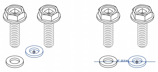
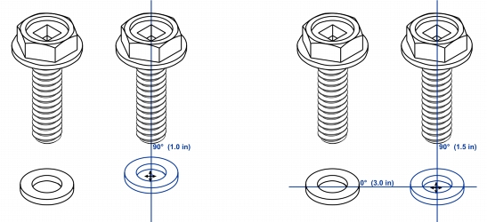
A dynamic guide was displayed from a node in the bolt on the left. The screen tip next to the node displays the angle of the dynamic guide(0º) and the distance between the node and the pointer (1.5 inches). The bolt on the right was dragged along the dynamic guide and positioned precisely 1.5 inches away from the node that was used to generate the dynamic guide.
Dynamic guides contain invisible divisions, called ticks, to which your pointer gravitates. Ticks let you move objects along a dynamic guide with precision. You can adjust tick spacing to suit your needs, and you can disable snapping to ticks. You can set other options for dynamic guides. For example, you can choose to display dynamic guides at one or more preset angles or at custom angles that you specify. You can preview the angle settings. You can also customize the color and line style of dynamic guides. When you no longer need a dynamic guide at a certain angle, you can delete the angle settings. You can also display dynamic guides that are extensions of line segments.
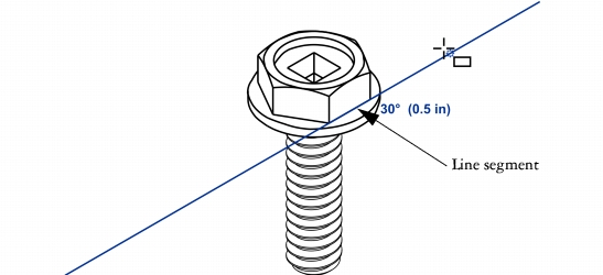
This dynamic guide is an extension of a line segment.
You can turn off dynamic guides at any time.
| To enable or disable dynamic guides |
1. |
Click Tools |
2. |
In the Alignment and dynamic guides docker, enable or disable the check box in
upper-right corner of the Dynamic guides section.
|
You can toggle dynamic guides on and off by pressing Shift + Alt +D.
|
| To display dynamic guides |
1. |
With dynamic guides enabled, click a drawing tool.
|
2. |
Move the pointer over and then off a node, center, quadrant, or text-baseline snap
point of an object.
|
3. |
Repeat step 2 with other objects to display other dynamic guides.
|
The snap points you point to are registered in a queue and used to create dynamic guides. |
The node, center, quadrant, and text-baseline snap points appear only when
the corresponding gravity modes are activated. For more information about
snap points and gravity modes, see Using gravity snapping.
|
You can avoid displaying too many dynamic guides by clicking in the drawing
window or by pressing Esc. Either of these actions clears the queue of points.
|
You can use the snap points you registered to display intersecting dynamic
guides. First, display a dynamic guide, and then move the pointer along it to
where an intersecting dynamic guide would be displayed from a registered snap
point.
|
| To position an object in relation to another object |
1. |
With dynamic guides enabled, select an object.
|
2. |
Drag the object to a node, center, quadrant, or text-baseline snap point of the
target object.
|
3. |
When the snap point of the target object becomes highlighted, drag the object
along the dynamic guide to position it.
|
The node, center, quadrant, and text-baseline snap points are displayed only
when the corresponding gravity modes are activated. For more information
about snap points and gravity modes, see Using gravity snapping.
|
| To draw an object in relation to another object |
1. |
With dynamic guides enabled, click a drawing tool.
|
2. |
Move the pointer over a node, center, quadrant, or text-baseline end-node snap
point of an object.
|
3. |
When the snap point becomes highlighted, move the pointer to display a dynamic
guide.
|
4. |
Move the pointer along the dynamic guide to the point where you want to draw,
and drag to draw an object.
|
| To draw parallel lines |
1. |
Click Tools |
2. |
Ensure that the Generate parallel guides button is enabled.
|
3. |
Draw a straight line or an object that contains straight line segments.
|
4. |
Using the 2-point line tool
|
5. |
Move the pointer back to where you want to draw the parallel line.
|
6. |
When a parallel dynamic guide appears, continue to drag along the guide until the
line is the length you want.
|
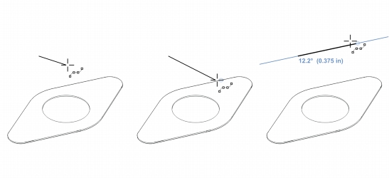
To draw a parallel line, start drawing a straight line (left). Next, move the pointer over the edge of a straight line segment (middle). Finally, move the pointer back until a parallel dynamic guide appears, and drag along the guide until the parallel line is the length you want (right).
With the help of parallel dynamic guides, you can use the 3-point rectangle
tool
|
| To position an object at the intersection of dynamic guides |
1. |
With dynamic guides enabled, select an object.
|
If you want to move the object by a specific snap point, move the pointer over the snap point until the point becomes highlighted. |
2. |
Drag the object to an eligible snap point on another object, and continue to drag
until a dynamic guide appears.
|
Don’t release the mouse button. |
3. |
Drag the object to another eligible snap point, and don’t release the mouse button.
|
4. |
When the snap point becomes highlighted, continue to drag until another dynamic
guide appears where the two dynamic guides would intersect.
|
5. |
When the intersection point appears, release the mouse button.
|
| To set options for dynamic guides |
1. |
Click Tools |
2. |
In the Alignment and dynamic guides docker, click the Dynamic guides button
|
3. |
Perform one or more tasks from the following table.
|
|
|
Copyright 2013 Corel Corporation. All rights reserved.